


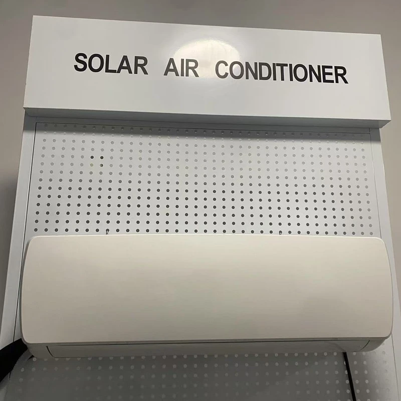
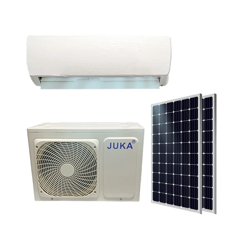
|
24,000
BTU NOMINAL
|
48 V
DC BUS VOLTAGE
|
|
7.0 kW
COOLING, CONVERTED
|
0
GRID CONNECTIONS REQUIRED
|
Most buyers arrive at this category already knowing the number they want. They have a room, they have a rule of thumb about BTU per square metre, and they ask for the unit that matches. That is a sensible way to buy a mains powered air conditioner, because the electricity is somebody else's problem. It stops being sensible the moment the electricity is yours.
A 24,000 BTU machine is roughly seven kilowatts of cooling. To deliver that, the compressor and fans draw a certain number of watts, continuously, for as long as the room is above set point. In a grid connected house that shows up as a bill. In an off grid house it shows up as battery state of charge at four in the morning, and as the number of panels on the roof. The panel count is the real specification of an off grid air conditioner, and it is set by the DC efficiency of the unit, not by its BTU figure.
24,000 BTU is the same as about 7.0 kW of cooling capacity. As a rule of thumb, that is the class of unit used for a large living room, an open plan kitchen and dining space, a small shop floor, a consulting room, or two connected bedrooms in a hot climate. The number is nominal: it is measured at a standard test condition, and every unit delivers a little less when the outdoor air is hotter than the test point and a little more when it is cooler. That is true of every brand and every model, and it is the reason a 24,000 BTU unit that feels weak in a 40 °C afternoon is not necessarily faulty.
What matters for sizing is not the headline number but the relationship between the room and the outdoor coil. A room with west facing glass and a dark roof needs more capacity than the same floor area on a shaded ground floor. A room with a ceiling fan and good insulation needs less. If you are choosing between 18,000 and 24,000 BTU for a space that sits on the boundary, the larger unit will reach set point faster and then cycle, which is fine on grid power and wasteful on a battery, because the pull down is the most expensive part of the day.
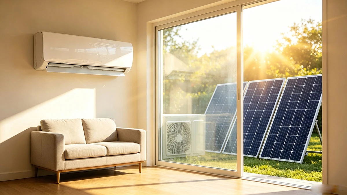
| Room type | Typical fit | What decides it |
|---|---|---|
| Open living and dining | Strong | Ceiling height up to 3 m, one indoor head, door kept closed |
| Shop or clinic front room | Strong | Door traffic, glass frontage, signage heat load |
| Two bedrooms, door open | Possible | Airflow between rooms, night time use only |
| Container office or cabin | Careful | Steel skin heat gain, no shade, thin insulation |
A conventional solar installation puts an inverter between the panels and the house, and the air conditioner then runs on 230 V AC as if nothing had changed. Each conversion in that chain costs energy. A DC driven unit takes the array voltage, regulates it to a 48 V DC bus, and feeds the compressor and the fans from that bus directly. There is no inverter stage between the sun and the compressor, which is why a DC unit of the same nominal capacity can be run from a smaller array than an AC unit plus inverter.
The 48 V level is also the reason the cabling is manageable. At 48 V the current for a given power is four times lower than at 12 V, so the copper stays reasonable and the voltage drop across a ten metre run stays small. It is the same reason 48 V has become the default for off grid homes, telecom sites and small commercial solar systems.
| Stage | Component | What it does |
|---|---|---|
| 1 | PV array | Produces the DC input; tilt set to the latitude of the site |
| 2 | 40 A DC breaker | Isolates the array from the controller for service |
| 3 | Charge controller | Regulates array voltage to the 48 V bus, and manages charging |
| 4 | 40 A DC breaker | Protects the battery cable between controller and battery cabinet |
| 5 | 48 V battery bank | Optional. Carries the night load, sized separately from the array |
| 6 | KF-70GWS | Runs the compressor and fans from the same 48 V bus |
Two details from the installation guide are worth repeating here, because they are the ones installers get wrong. First, a 40 A DC breaker belongs on both sides of the controller, not just one: one between the panels and the controller, one between the controller and the battery cabinet. Second, the cable from the controller to the battery cabinet is specified at 4 mm² in the manual, and it should be run as a pair with the breaker close to the battery end, so that a fault in the run cannot be fed by the bank.
A split system separates the noisy half from the quiet half. The indoor unit carries the evaporator coil, the fan and the louvres, and it hangs on the wall of the room being cooled. The outdoor unit carries the condenser coil, the compressor and the condenser fan, and it stands where it can reject heat to open air. The two are joined by an insulated copper pair, a condensate drain and a multicore cable. Almost everything that goes wrong at commissioning is in that join.
Both copper ends are flare connections. The manual calls for two spanners, one to hold the body of the fitting and one to turn the nut, because a single spanner twists the pipe and work hardens the flare. A vacuum pump and a pressure gauge are on the tool list for the same reason: the line set has to be evacuated before the charge is released, and it has to hold pressure before the unit is started. None of this is exotic, but all of it is invisible once the trunking is closed, which is why the photographs in the guide concentrate on the moment before the wrap goes on.
| Connection | Runs from | What the installer checks |
|---|---|---|
| Liquid line | Indoor flare to outdoor flare | Flare square and burr free, nut torqued with two spanners |
| Suction line | Indoor flare to outdoor flare | Same, plus insulation continuous to the service valve |
| Condensate drain | Indoor tray to outside | Fall of at least one in fifty, no uphill section, outlet below tray |
| Interconnect cable | Indoor terminal block to outdoor L, N, 1, 2, 3 and earth | Numbered cores matched one to one, earth landed on both ends |
| Trunking | Whole run | Line set, drain and cable wrapped together with tape, no kinks |
The wiring order matters on a DC unit more than on a mains unit, because the control boards are alive as soon as the bus is up. Land the earth first, then the numbered cores, then check that the numbers match at both ends before the outdoor cover goes back on. The guide shows the terminal strip with L, N, 1, 2, 3 and an earth stud, and it is worth taking a photograph of that strip at commissioning: it is the single most useful record if the unit is ever serviced by somebody else.
The indoor unit is fixed to a steel wall plate, and the plate is fixed with four expansion screws. Before drilling, three things decide whether the installation will be quiet and dry for the next decade: the height, the drain route, and what is on the other side of the wall.
Height: the head should sit high on the wall, with the top of the unit far enough below the ceiling that the air intake is not starved. A unit pushed into a ceiling corner will run, but it will pull its own return air and the room will feel flat. Drain route: gravity is the only pump in this system, so the drain must fall continuously from the tray to the outside. If the only exit is above the tray, the installation needs a condensate pump, and that is a different job. Other side of the wall: the copper pair leaves through a single sleeve, and the outdoor unit needs to be within the line set length and reachable for service. Drilling a 65 mm sleeve in the wrong place is the most common reason a one day installation becomes two.
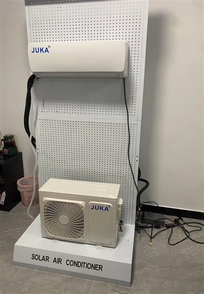
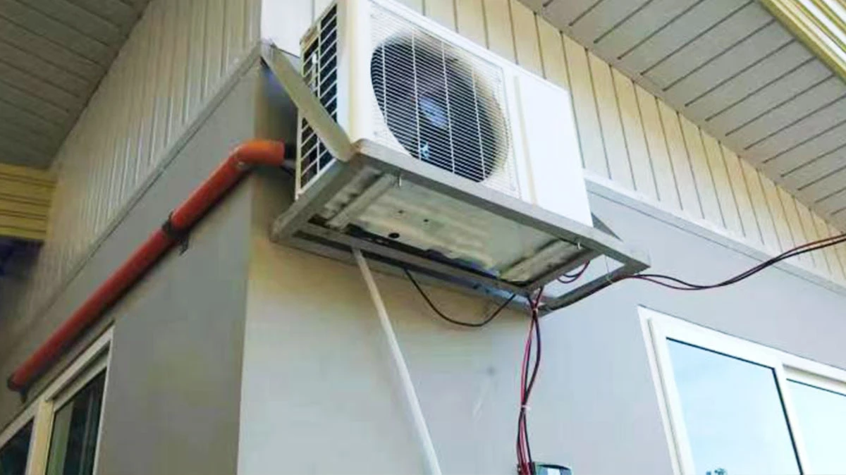
The outdoor unit is a heat rejector, and it can only reject heat into air that is cooler than its coil. Everything about siting follows from that sentence. It needs free air on the coil face, free air out of the fan, and it must not sit in a recess that lets hot air circulate back into its own intake. A unit installed in a closed balcony will run continuously, never reach set point, and draw more from the battery than the array can replace.
In hot climates, shade over the unit is worth more than any other single measure. A condenser in direct afternoon sun starts from a higher condensing temperature before it has done any work at all. A simple roof over the unit, open on three sides, is enough. Wall brackets are acceptable where floor space is unavailable, but the bracket must be rated for the weight of the unit and the wall must be able to take the pull out loads: a hollow block wall needs through bolts or a spreader plate, not plastic plugs.
| Siting question | Good answer | What it costs if ignored |
|---|---|---|
| Air on the coil face | Open on both faces, nothing within a fan diameter | Higher condensing pressure, longer run time, more amps |
| Recirculation | Fan discharge not aimed back at the intake | Unit chases its own hot air and never reaches set point |
| Sun | Shaded roof, open on three sides | Capacity lost exactly when it is needed most |
| Service access | Valves and electrical cover reachable without removing the unit | Every future visit starts with a dismantle |
| Drain from indoor | Drain terminates below the tray, away from the coil | Water stains the wall or drips into the condenser |
A 48 V DC system is safe to touch but not safe to short. A battery bank will deliver its short circuit current without complaint until something melts, so the protection is not optional and it is not a single device. The installation guide asks for a 40 A DC breaker between the battery and the charge controller, and a second 40 A DC breaker between the charge controller and the solar panels. That gives three islands: array, controller, battery. Any one of them can be isolated without the others being live at the far end.
The cable between the controller and the battery cabinet is specified at 4 mm². That is the minimum for the currents this unit class draws over the short run inside a plant room; if the battery cabinet sits further away than the typical layout, the installer should calculate the drop rather than assume. The rule that matters is the one in the manual: the breaker goes close to the battery end of the cable, so the length of unprotected conductor is as short as possible.
| Item | Specification | Source |
|---|---|---|
| Array breaker | 40 A DC, between panels and controller | Installation guide |
| Battery breaker | 40 A DC, between controller and battery cabinet | Installation guide |
| Battery cable | 4 mm² pair, controller to battery cabinet | Installation guide |
| Interconnect cable | Multicore L, N, 1, 2, 3 plus earth, indoor to outdoor | Outdoor terminal block |
| Wall plate | Four expansion screws, plate level before the head is hung | Indoor bracket detail |
| Line set | Insulated copper pair, flare both ends, vacuum before release | Flare detail |
The honest way to size an off grid air conditioner is to work from the nameplate and the load profile, not from the BTU figure and not from a table somebody published for a different climate. The nameplate gives the input power. The load profile is how many hours a day the compressor actually runs, which in a hot climate is longer than the hours the room is occupied, because the unit has to pull the room down first.
The arithmetic has four lines and they are all multiplication and division:
| Line | What you enter | Where it comes from |
|---|---|---|
| 1. Daily energy | Input power (W) × running hours ÷ 1000 = kWh per day | Nameplate plus your own duty cycle |
| 2. Array size | Daily kWh ÷ peak sun hours ÷ 0.75 = kW of panels | Local peak sun hours, worst month |
| 3. Battery | Night kWh ÷ depth of discharge = kWh of storage | Chemistry chosen for the site |
| 4. Controller | Array kW ÷ 48 V, with headroom for cold mornings | Controller datasheet |
The 0.75 in line two is the part buyers forget. It covers dirt on the glass, cable loss, controller loss and the fact that a panel rated at 550 W does not produce 550 W at nine in the morning. It is not a safety margin for a bad design; it is the ordinary derating that makes a design honest. Use the worst month of the year, not the annual average, because the unit will be needed most in exactly the month the sun is weakest in the northern hemisphere winter and the heat is highest in the southern hemisphere summer.
If the arithmetic produces a number that looks large, that is the answer talking, not a fault in the method. A 24,000 BTU class unit running ten hours a day is a serious daily load, and the array that supports it should look serious. The alternative, undersizing and hoping the battery carries the shortfall, is how off grid cooling gets a reputation for not working.
Commissioning is a sequence, and the sequence is not negotiable. Each step exists to make the next one safe. The list below is the one we give to installation teams, and it follows the guide page by page.
| # | Step | Pass condition |
|---|---|---|
| 1 | Mount the wall plate level with four expansion screws | Plate cannot be rocked by hand; spirit level both axes |
| 2 | Run the line set, drain and cable through the sleeve | No kink, drain falls continuously outward |
| 3 | Flare both ends, torque with two spanners | Nuts seated, no cross thread, insulation continuous |
| 4 | Evacuate and hold vacuum | Gauge does not drift when the pump is valved off |
| 5 | Wire indoor to outdoor on L, N, 1, 2, 3 and earth | Numbers matched end to end, earth on both ends |
| 6 | Close up, tape the run, replace the outdoor cover | No exposed copper, cover screw fully home |
| 7 | Power the bus, start with the handset, check cooling and noise | Cold air within a few minutes, no rattle, drain running |
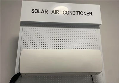
Step seven is where a competent installer and a fast one separate. A unit that is short of charge will still blow cool air for a few minutes and then fade as the coil ices. A unit with air in the line will sound slightly different at the compressor and will not hold its set point. Both faults are invisible from the room side and obvious from the gauge. If the installer does not own a vacuum pump, that is the moment to stop: everything before that step is reversible, and everything after it is not.
An air conditioner in an off grid house is maintained by whoever owns the house, so the list has to be short enough to actually happen. Four habits cover most of it: keep the filters clear, keep the condenser clear, keep an eye on the drain, and look at the controller reading once a month.
Filters: lift the front panel, take out the mesh, rinse it under a tap, let it dry fully before refitting. In a dusty climate that is a fortnightly job during the dry season and a monthly job in the wet season. A clogged filter does not just reduce airflow, it drops the evaporating temperature and makes the coil sweat in the wrong place, which is how a machine that was fine in year one starts dripping on the wall in year three.
Condenser: brush or vacuum the coil face from the outside in, and check that nothing has grown into the fan guard. In coastal sites the coil fins benefit from a rinse and a light protective spray every year. Drain: pour a cup of water into the indoor tray and watch it leave. If it hesitates, clear the line before the wet season rather than during it. Controller: read the daily yield figure once a month and compare it with the month before. A sudden drop is either shade you did not have before, or a panel that needs cleaning.
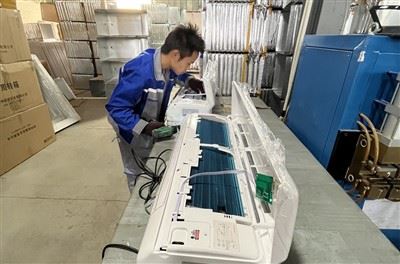
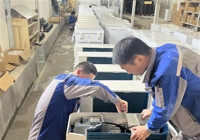
This is a large room unit, not a bedroom unit. It belongs where cooling is part of the business rather than part of the evening routine, and where the grid is either absent or unreliable enough that the array is already there for other reasons.
| Site | Why this size | What to watch |
|---|---|---|
| Rural clinic or health post | Waiting room and treatment room in one envelope | Door traffic; keep the outdoor unit off the patient side |
| Telecom or equipment hut | Rack heat plus ambient, cooling is a duty not a comfort | Run hours are long; size the array for continuous duty |
| Farmhouse main room | Large single space, high ceiling, west glazing | Shade the west wall, close the doors at peak |
| Container office | Small floor area but brutal skin heat gain | Add a second skin or roof shade, or the unit never rests |
| Island lodge or guest house | Communal lounge, daytime and evening load | Salt air, so rinse the coil yearly and check the bracket |
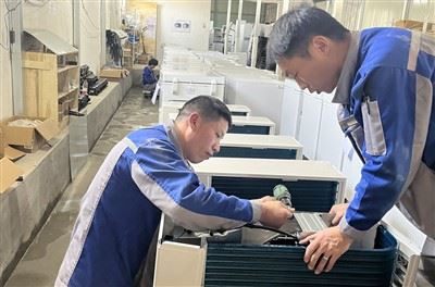
| Item | KF-70GWS |
|---|---|
| Cooling capacity | 24,000 BTU nominal, about 7.0 kW |
| System type | Wall mounted split, indoor head plus outdoor condenser |
| Power supply | 48 V DC, off grid bus |
| Compressor | DC driven, fed from the 48 V bus |
| Charge controller | External 48 V unit; CM3048 shown in the installation guide |
| Protection | 40 A DC breaker array side, 40 A DC breaker battery side |
| Battery cable | 4 mm² pair, controller to battery cabinet |
| Interconnect | L, N, 1, 2, 3 plus earth, indoor to outdoor |
| Line connection | Flared copper pair, vacuum before release |
| Condensate | Gravity drain from the indoor tray |
| Control | Infrared handset, wall head display |
| Mounting | Steel wall plate, four expansion screws |
| Refrigerant | Stated on the order confirmation for the build |
| Unit dimensions | Indoor and outdoor, stated on the order confirmation |
| Net and gross weight | Stated on the order confirmation |
| Packing | Two cartons, indoor and outdoor, dimensions on the order confirmation |
We keep the dimensional and charge data on the order confirmation rather than in this page, because this unit is built in more than one configuration for different markets and a single figure printed here would be wrong for somebody. If you need the numbers before you quote a project, ask us for the build sheet for your destination and we will send the exact figures with the drawing.
| In the cartons | Notes |
|---|---|
| Indoor unit with wall plate | Plate packed with the head, screws in the accessory bag |
| Outdoor unit | Separate carton, service valves capped |
| Infrared handset | Batteries not fitted in transit |
| Installation guide | Pictorial, English, follows the seven step sequence above |
| Accessory bag | Expansion screws, drain joint, insulation tape |
| Not included | Panels, controller, battery bank, breakers, line set length beyond the order |
| Does the unit need a battery to run? | It will run from the array through the controller whenever the array is producing, and that is how many daytime sites use it. For evening and night running you need a 48 V battery bank, sized for the night load. The two are separate decisions. |
| Can I use the 48 V lithium bank I already have? | Yes, if the controller can be set for that chemistry and the bank can deliver the starting current without the voltage collapsing. Send us the bank datasheet with the enquiry and we will confirm before you order rather than after. |
| Will it run on 220 V mains as well? | This is a DC unit and its compressor is fed from the 48 V bus. Running it from mains means putting a rectifier or an inverter and charger in front of it, which is a system design decision, not a plug. Tell us the site and we will quote the right arrangement. |
| How many panels do I need for 24,000 BTU? | Work it out from the nameplate input power and your duty cycle using the four line method in STAGE 08. Anyone who quotes a panel count without asking your running hours is guessing. |
| Can one array feed two units? | Yes. The bus is shared, so the array and the controller are sized for the combined load and each unit keeps its own breakers. Two heads on one bus is a common layout for a shop with a back office. |
| Does it heat as well as cool? | The standard build is a cooling unit. Heating options depend on the build for your market and are confirmed on the order, not assumed from the model number. |
| Who installs it? | A refrigeration technician with a vacuum pump, gauges and two spanners. The guide is written to be followed by a technician rather than by the end user, and the flare and evacuation steps are the ones that decide whether the unit lasts. |
| What about the drain in a dry climate? | Condensate is lower when the air is dry, but the drain still needs a continuous fall. In very dusty sites the tray is the first thing to silt up, so put it on the maintenance list rather than waiting for a stain on the wall. |
Inside the factory that builds this system
|
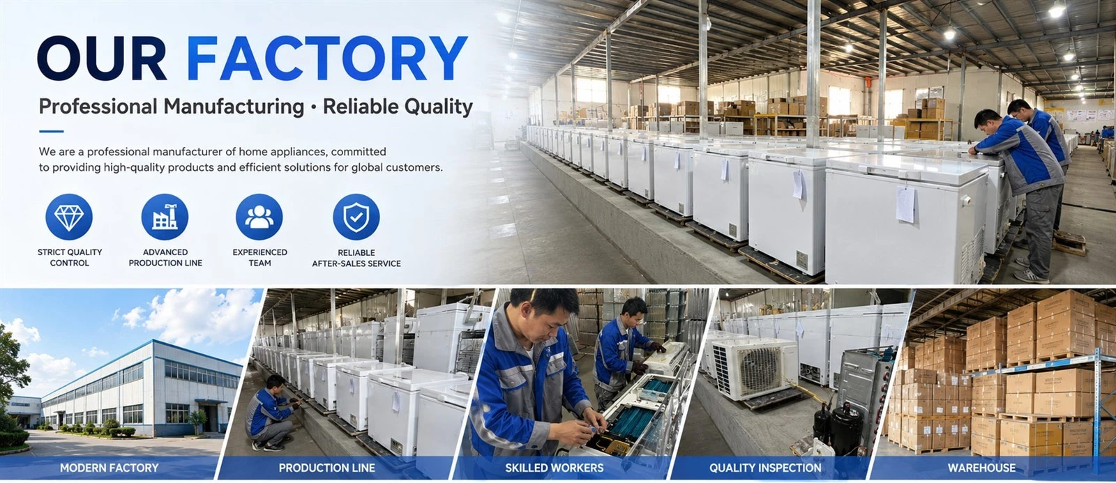
Hangzhou Juka Solar Technology was founded in 2015 around one problem: putting solar energy, new energy and smart control to work inside a refrigeration circuit. The range has since grown from a single DC chest freezer to solar refrigerators, solar ice makers, mobile ice-cream carts, delivery tricycles and beverage retail carts - all of them exported, most of them to Belt and Road markets. The work does not stop at the container. Partners in Ghana, Gabon, Cameroon, Nigeria, Kazakhstan and India are supported in setting up their own local production for retail and delivery refrigeration, which is how a cold chain becomes permanent rather than a series of one-off shipments. For a solar system this matters more than for a mains-only freezer. Panel sizing, controller rating and battery capacity all depend on cabinet volume and site conditions, so the cabinet and the electronics are engineered together instead of being bought separately by the importer. |
 |
What is decided before the cabinet is built
|
Wall thickness is a production parameter 65 mm or 110 mm foam is set on the foaming line, not assigned in a brochure. Insulation that is specified but not achieved is the usual reason a solar cabinet underperforms in its first hot season. |
One bill of materials Panel, controller, battery and cabinet are listed together, so the importer receives a system whose parts were sized against each other rather than sourced independently. |
|
Voltage as an order option DC input, AC adapter voltage, plug type and control panel artwork are selected per market on the same platform - no separate tooling run for a different destination. |
Repeatable on the second container Foam thickness, fittings and controller model are held per customer, so a follow-up order matches the first one instead of drifting. |
Certification and test documentation
CE marking covers the electrical arrangement, and utility model patents cover the cabinet and the direct-drive control layout. Documents travel with the order so they can be presented at customs and to institutional or tender buyers.

CE - low voltage and EMC |

CE - supplementary schedule |

Utility model patent - cabinet structure |
On the floor
 |
 |
 |
 |
Six control points behind every cabinet
|
01 |
Foaming runs inside a constant 20-23 °C room, so the foam quality does not shift with the season. |
|
02 |
Condenser and evaporator are nitrogen purged before any pipe joint is made, keeping the internal circuit clean. |
|
03 |
Vacuum is pulled to below 20 Pa. A unit that does not reach spec is never charged with refrigerant. |
|
04 |
Two leak tests per cabinet with an INFICON detector - one unpowered, one running. |
|
05 |
A constant-temperature test room confirms refrigeration parameters under identical conditions all year. |
|
06 |
Production and quality control are separate departments. Only cabinets signed off by a QC inspector are packed and warehoused. |
Machines on the line
|
Equipment |
What it gives the buyer |
|
Automatic laser cutting machine |
Consistent panel geometry, tight tolerances, clean edges |
|
Punch press and bending machine |
Repeatable cabinet forming from unit to unit |
|
Dual-gun high-pressure foaming machine |
Even density across the whole cabinet, no thin spots |
|
CACL high-precision filling machine |
Precise refrigerant charge on every unit |
|
INFICON high-sensitivity leak detector |
Finds leaks that ordinary detectors pass |
OEM, ODM and local assembly
Cabinet-only supply, private label, SKD and CKD shipments are all available, together with technical guidance for partners who would rather assemble locally than import finished units. Helping partners build their own refrigeration business is the part of the work that outlasts a single purchase order.
What can be changed on a standard order:
✓ Customer logo and cabinet colour
✓ Voltage options and plug type
✓ Packaging design
✓ Product configuration, baskets and fittings
✓ Panel, controller and battery included, or cabinet supplied on its own
Hot Tags: air conditioners for home, China air conditioners for home manufacturers, suppliers, factory


